In this article the two different methods of defining contact in MSC Nastran will be explained and discussed.
Contact can be a useful tool when performing FEA simulations. It allows the interaction between multiple bodies without adding additional elements to the model. By adding the contact condition to a model correctly it is possible to create a model that more realistically represents reality. However, by adding contact to a model, it might cause the analysis not to complete because of the added computational complexity and the number of things the analyst has to take into account.
By default, Nastran does not assume contact exist between all bodies in a model, simply because of the computation cost involved in checking for contact between every element and every other element in a model. This can however be specified, at the expense of the run times, but another reason why this is not specified by default is because different contact conditions such as varying friction values might exist throughout the model and therefore the analyst needs a means to specify and control it.
Contact in a model is applied mathematically and unless otherwise specified, Nastran defaults will be used that are suitable for general contact cases. Default parameters will in most cases be sufficient, however, it might cause problems under more complex or less common scenarios or induce unnecessarily longer solving times if the analyst doesn't understand these parameters and set them incorrectly.
Figure 1: Gear set stress plot
Contact Definition Method
Before discussing contact in Nastran, it should be noted that there are two possible methods of specifying contact in Nastran. The two contact methods are:
- Contact table method (BCTABLE)
- Contact Pairs method
Click on Figure 2 to view the process of defining contact with both the Contact table method as well as the Contact Pairs method.
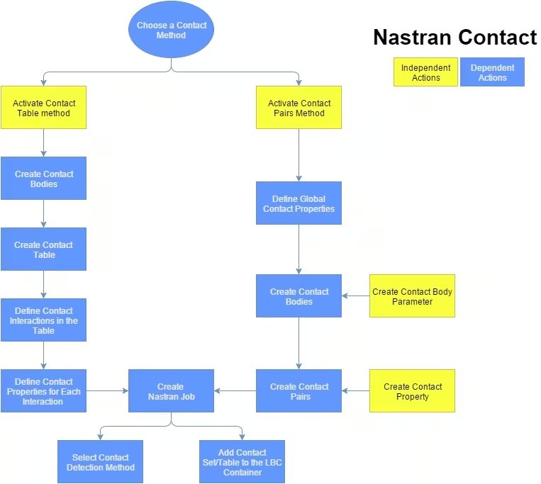
Figure 2: Process of defining contact using the contact table or contact pairs method
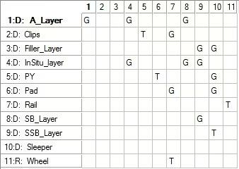
The intent behind the two methods of defining the contact interactions between bodies is that with the original, contact table, method of specifying contact, it becomes rather complicated to define the contact interactions between many bodies in the contact table without making any mistakes, with Figure 3 as an example of this. Because of this a new method was introduced where the contact pairs can be created directly and instead of specifying contact parameters for each pair, contact interaction can be defined and simply referenced for each pair. This makes it easier to define the contact condition for a large amount of contact bodies.
Both methods of applying contact will have the same outcome but with the contact table it is easier to define contact for a small number of contact bodies, whereas the contact pairs method will be easier to define contact for a large number of contact bodies.
So which method should be used?
The answer is that both methods have their own merits. Any one of the two methods can be used for any model although it is recommended to use the contact table for a model with a small number of contact bodies and contact pairs for a model with a large number of contact bodies. Whichever you choose for your model, keep in mind that the other option is available and can be used if the current method is posing difficulties.
For more on the process of defining contact view the contact section of FEA basics and SimXpert for the Contact Pairs method and Supplementary FEA Tutorials for the Contact Table method. These shows how to set up Nastran contact using MSC SimXpert although a similar process is used with MSC Patran.
Contact Types
Two types of contact interaction exist between two bodies namely Glue and Touch contact. Although there are variations in how these contact interactions are applied depending on the software used, these remain the two main contact interactions.
Glue contact:
- Glue contact is an ideal option to use in a model with multiple parts in a structure. It allows two bodies to be fixed at the contact surface without having the elements of both bodies be the same size and attempting to have the nodes on the two surfaces match.
- It can be applied as a linear contact which means that two element faces remain in contact no matter what happens with the structure around it. As long as the contact condition is detected between two bodies, this will not cause for a longer analysis time and it should not cause further struggle with the model.
- Glue contact can also be applied with certain conditions. For instance, it can be specified that if the stress on the contact surface exceeds a specified stress, the contact should be released and for the remainder of the analysis be treated as a broken contact.
Touch contact:
- Touch contact is a valuable tool to use in FEA models although it comes with the cost of a much longer analysis time and it does require additional considerations to ensure that the model solves successfully.
- With this method of contact, the parts in the model can move as it is allowed to by the constraints on the body, however with touch contact active between two bodies the additional condition is that the one body is not allowed to penetrate the other. With the movement of the body allowed it is therefore important to consider the position of one body relative to another.
Contact Bodies
Now that the types of contact are introduced, these types of contact can be applied between various types of bodies in various combinations. Contact bodies can be created from:
- 3D/2D/1D deformable contact bodies
- 3D/2D rigid contact bodies.
Deformable and Rigid contact bodies are just as the name suggests. A deformable contact body is a normal FEM body that can deform and experience stresses while in and due to contact. A rigid contact body is a useful method in which the body is assumed to remain rigid during the simulation which means no calculations are performed for the inside of the body. This simply means you can have a body in the analysis which affects the rest of the structure without adding significant time to the analysis.
- Deformable contact bodies
For any deformable contact body with a non-square shape or a shape that is not exactly captures by the elements, analytical edge discontinuities can be activated when creating the contact body. Analytical edge discontinuities is a function that Nastran uses to determine the possible true curvatures of the edge that could not be captured accurately by the elements and uses this shape when determining contact. An example of this is two circular objects in contact. Since the circular objects will consist of a number of straight lines or faces it is difficult to have an accurate distributions of the forces acting between the two bodies. The contact might be applied only to some of the faces or have inconsistencies in the contact forces. Although this might affect the results somewhat, this will also make it difficult for Nastran to correctly detect the contact or fail to detect the contact at all. With analytical edge discontinuities Nastran uses the change in angle between the two element faces to construct a closer to circular contact surface.
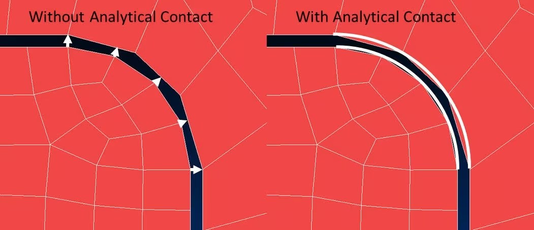
Figure 4: Analytical Contact
As stated earlier the rigid contact body is applied to add the required stiffness to the model without adding additional solving time. Since a rigid body is simply geometry that is specified as a body, there are no nodes on the body to either constrain or apply a load to that body. For this reason, additional steps have to be added when creating a rigid contact body.
The first thing to add when creating a rigid contact body is to specify how the body will be controlled by specifying either velocity, position or load controlled. For the velocity and position controlled options the body will experience some type of controlled motion during the analysis which will in turn impose a load on a deformable contact body. This will typically be with a bending device where the deformation of a pipe is of interest for which only the pipe will be made deformable with the three pulleys modelled as rigid bodies. Two pulleys will therefore by fixed and the third have a movement which will apply whatever force is required. For the option of load controlled the body will act as any other body in the model for which a load or constraint can be applied to the body. In this case two nodes have to be created and linked to the body on which the constraints can be applied, one for the translations and the other for rotations.
For rigid contact bodies the approach velocity function is available to assist the initial contact to be detected in the model. With this a direction is specified for which Nastran will move the rigid body in this direction until contact between rigid and deformable bodies are detected before a load is applied, thereby ensuring that the contact condition is met at the start of the analysis.
When creating a rigid contact body, it is important to check the inward normals of the contact body. This will show an arrow that points in the direction of the solid part of the rigid body and it is therefore very important that the arrow points in the correct direction.
Defining Contact Interactions
When defining the contact interaction between two contact bodies, whether with a contact table or contact pairs, some contact properties can be selected to help with the contact detection.
- Slave and Master Option Flag
The Slave and Master Option flag is a tool that specifies where the contact is applied to. In this option select the A=1 for all 3D contact bodies, which will specify that contact should occur on the outside surface of the contact body, whereas for 1D and 2D contact bodies some other options are available. These include options such as which side of a shell element should be in contact or whether the edges of a 1D element should be included.
Coordinate Modification is a useful tool that will allow Nastran to move nodes (within a tolerance distance) to avoid some contact problems that might occur. Two options are available here with the combination of both options available as the third.
In the case of stress free initial contact, nodes are moved in the beginning of the analysis to ensure that the analysis will start with the nodes in contact. For this option, the nodes will be moved if either the nodes are already penetrating the contact bodies or a small gap is exist between the two bodies. The nodes will then be moved (within the tolerance distance) until the nodes are aligned.
The delayed slide-off option will be active during the entire analysis to align two nodes, on the edge of a contact surface where one node would “miss” the other contact body and therefore have penetration of the node on the corner.
These two options along with a combination of the two can be activated in the contact table for every contact group or in the geometric properties for the contact pairs method.
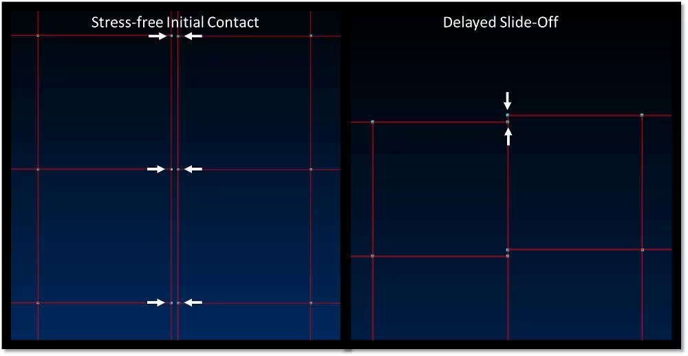
Figure 5: Coordinate Modification
Contact Settings for a SOL400 Analysis
When creating a SOL400 analysis, under the solver control settings or in the BCPARA Nastran entry, the type of contact detection is specified with the Nastran default as Node-to-segment contact. The alternative is the segment-to-segment contact method both of which will be discussed here.
- Node-to-segment contact detection
As the original contact detection method Node-to-segment contact works on a Master-slave basis with one body being defined as the master and the other as the slave. The rule for the contact is that the nodes of the Slave body cannot penetrate the element faces of the Master body.
A common problem that can occur in this case is that for a large difference in element size an incorrect master-slave configuration is selected which will mean that nodes from the Master will penetrate the slave body and cause incorrect contact results since the contact rule has not been broken. It is therefore important to always choose the body will the smaller element size to be the slave body. In cases where this might still be a problem, there is the option to select double sided contact which means that both bodies will be checked for contact to avoid this problem. This will however result in the contact condition being checked twice per calculated increment and might increase the analysis time significantly.
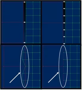
Figure 6: Result of an Incorrect Slave-Master Definition
- Segment-to-Segment contact
The alternative method for contact detection is the Segment-to-Segment contact detection method which tends to result in easier contact detection. This method adds additional points to the element face and checks the contact between these point and therefore allows for a larger difference in element size on the contact surface. With this method the Master-Slave concept does not exist and both bodies are checked for contact. The Segment-to-Segment contact method is the new method of contact and is also the preferred method.
With Segment-to-Segment contact comes two options namely Small-Sliding Segment-to-Segment and Large-Sliding Segment-to-Segment contact. The difference between these two methods are just as the name suggest. For models where the contact bodies do not move relative to each other, such as the bending of a plate around a cylinder the Small-Sliding option is sufficient since the same elements will be in contact during the analysis.
However, for a model with large relative movement between elements in contact, such as in roller bending, the elements in contact have to be redefined for every increment and therefore the Large-Sliding option has to be used.
For models such as these the large displacements option (LGDISP Nastran entry) should be used along with the contact condition.
The Large-Sliding option can however be used for any model with Large or Small-Sliding while the Small-Sliding option will only be sufficient for a model with Small-Sliding contact.
General Contact Considerations
When running an analysis that contains contact, whether it is glue or touch contact, there are certain considerations to be made for the model itself in order to ensure that the contact condition is applied correctly.
- It is always a good idea to start by using a small version of the model in order to test whether the model is set up correctly. This applies to models with contact especially since touch contact will significantly increase the solving time, which will result in an unnecessary loss of time if an analysis fails or produces incorrect results due to an error with the contact condition.
- Although it is theoretically possible to have elements on the contact surface that vary greatly in size, this is not always the case. Some errors have been found in detecting the contact correctly when the size of the element faces on the contact surface varied too greatly. This is simply because you are trying to have contact between one surface that has for example: fifty contact points with another surface with only 5. Although it should be possible to find the contact, it is possible that a few of the elements are missed when checking the contact. The different sizes of elements can be further evaluated to find the required element size for the contact surface however a good starting point is to have a maximum of five elements on one surface in contact with one element on the other surface.
- A possible way to decrease the size of the elements on the contact surface without increasing the total amount of elements significantly is to separate the section in contact from the rest of the body and only increase the amount of elements in that section and apply self-contact to that body. This will allow the element size to gradually reduce from the one body to the next across the contact surface.
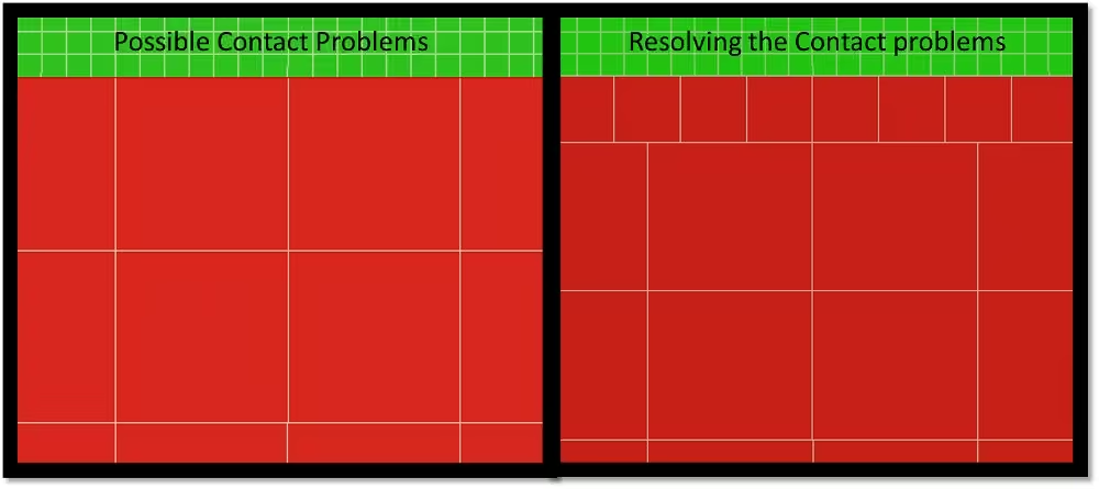
Figure 7: Elements on the Contact Surface
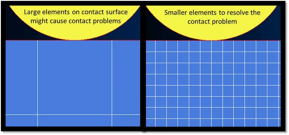
Figure 8: Rigid to Deformable Contact Elements
- Another case is when applying a linear motion to a rigid body for a model where the rigid body is moved over a deformable body and a load being applied at each step after the body is moved. In order to select an appropriate distance to move in each step (by choosing the step size) it is important to select a distance small enough that the rigid body does not move into the deformable body due to the deformation of the deformable body. Although having smaller time steps will increase the number of steps to solve for and therefore increase the total analysis time, having too large steps will either cause the analysis to fail or have an even longer analysis time in order to solve the penetration condition.It is therefore important to choose a number of steps for the analysis by considering the distance that the rigid body will move in each step as well as the size of the elements on the contact face.
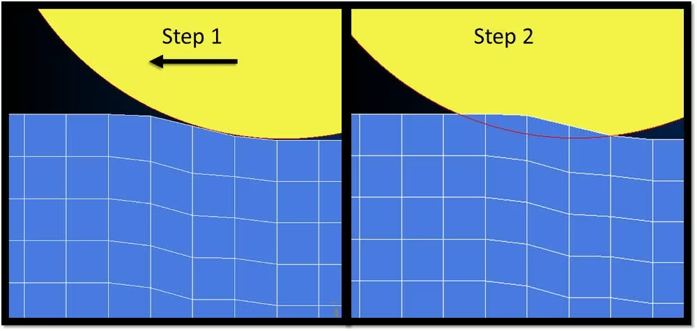
Figure 9: Analysis Step Size
Applying contact to a model correctly can therefore allow you to decrease the analysis time by reducing the total amount of elements. Alternatively it is possible to create a more realistic model by including a realistic interaction between bodies in your model.


