This document describes how to generate an MNF for use as a flexible body in ADAMS or Vi-Rail using Patran
In Patran, create the FEM of the part required for the problem:
- In the material properties, density has to be specified in order to run a “normal modes” analysis.
- Identify all the nodes that will be the interface points to the rest of the system in Adams/Vi-Rail via connections or springs and dampers.
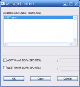
- Create a “Degrees of freedom” List as shown below; this will define the interface nodes of the component. (Under “Meshing”, select “Create” and for “Object” select “DOF List”).

Interface points on FE part
- Enter a name for the DOF List to be created.
- Under “Define Terms”, for “Node List”, select the nodes where attachments will be made in the Adams/VI-Rail model.
-
-
- NB: The selected nodes in the FEM have to be able to transfer all forces and moments in the 6 degree of freedom (DOF) directions. i.e: Do not only select a single node of a solid element since it does not transfer moments. On solid elements a number of nodes need to be connected to the single interface node using RBE2’s. The supported elements of which nodes may thus be selected as the interface nodes include CBEAM, CQUADR, CTRIAR, RBAR and RBE2's).
- Select all of the Degrees of freedom.
- Ensure that no constraints are present in the model as this will affect the stiffness of the part. Any applied loads will be ignored.
Setup the Analysis
Analysis set
Analysis setup
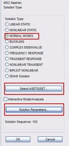
- Create a new analysis job
- Select “Analyze”, “Entire Model” and “Full Run”.
- For solution type select normal modes
- Open “Select ASET/QSET”. Select the DOF List created and click ok
- Open “Solution Parameters”.
- Select “ADAMS Preparation”
- For “ADAMS Output” select “MNF Only”.
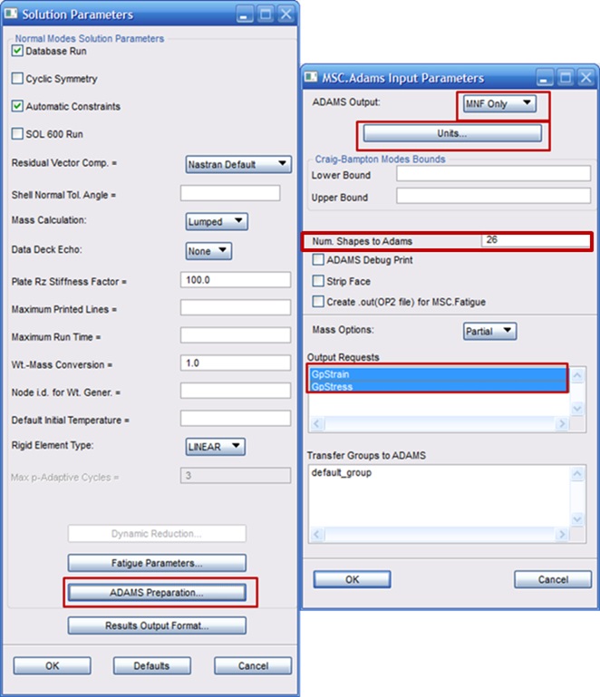
Analysis settings for Adams preparation
- NB: Open Units and select the appropriate units for the job.
- Enter the “Num. Shapes to Adams” (e.g. 10 or 26 etc).
- This determines the amount of mode shapes that will be calculated in addition to the stiffness modes between interface points. The possible amount of mode shapes that will be present in the MNF file, will now be: 10+(num. of interface nodes)x(6 for degrees of freedom of each). In the case of the model above: 26+(23x6)=164.
- Under Output requests, Select all of the options and select OK.
Select OK to close solution parameters
- Open subcases:
- Select the load case that has no loads or boundary conditions applied.
- Select “Output Requests”
- Under “Select Result Type, select “Grid Point Stresses.
- This will allow stresses to be calculated in ADAMS/VI-Rail.
- “GPSTRESSES=…” will now appear under the Output Requests list.
- Select “Apply” and “Cancel” to close “Output requests”.
- Open “Subcase Parameters”
- Under “Number of Desired roots”, enter the “Num. shapes to Adams” minus 6:
In this case 26 – 6 = 20

- Select Apply to run the Analysis.
- A “.mnf” file is then created that can now be used in ADAMS or VI-Rail to use as a flexible body.
See Using flexible bodies in Adams or Vi-Rail how to use the created MNF in Adams or Vi-Rail.


